Introduction to SCR:
SCR is abbreviation for Silicon
Controlled Rectifier. SCR has three pins anode, cathode and gate as
shown in the below figure. It is made up of there PN junction diodes
also; it is solid state equivalent of gas filled triode and has around
four semi conductor layers. SCR can conduct the current in a single
direction or we can say SCR’s are unidirectional. The SCR can be
triggered only at the gate through the current. SCR will combine the
features of rectifier and transistor. They are mainly used in switching
applications. They can also be triggered with the break over voltage (if
the forward voltage is more than the break down voltage of the
component). They are mainly used in the high voltage and high power for
controlling purpose. They are also used in the light dimming, voltage
regulators, motor control etc.
SCR Operating Modes:
- To turn on the SCR the small amount of voltage or voltage equal to break over voltage is required to the gate which will trigger the SCR and when the SCR is turned on, it will have very low resistance and allow the power to conduct and also increase the anode current. Even if we remove the gate voltage also it will be in conduction. The only way to make the SCR to turn off is to make the voltage to zero or make the current less than the handling current between the anode and cathode.
- There are two ways to turn on the SCR is the first way is to turn on by opening the gate and compensate the power supply to the break over voltage. And second way is to supplying the voltage to operate the SCR with less than break over voltage and applying the small amount of about 1.5V applied to the gate which will trigger the SCR.
- When the SCR is turned off it will have high resistance and restrict the current to the leakage current. To turn off the SCR from on state also have only one ways normally people think that if we stop the gate current the SCR will become turn off, but it will not this state is called “loss of control”, the only way is turnoff the SCR is reducing the supply voltage to zero.
Also Read the Post – 9v Battery Charger Circuit using SCR and LM311
SCR in Forward and Reverse Characteristics:
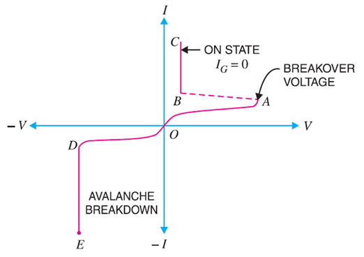
In Forward bias the anode will be at
positive terminal and cathode will be at negative terminal. The supply
voltage will increased from initial value zero when it reached to A as
shown in the graph below and start conduction from this point also it
there will be the voltage drop due to the load resistance and fall down
to point B. to turn on the SCR completely or for heavy condition small
current is required to the gate. This current triggers the gate and
switch on SCR and decreases the resistance and start conduction and goes
to point C.
In Reverse bias that is cathode will be
at positive terminal and anode will be at negative terminal at this
point there will be very small leakage current at anode . PEAK REVERSE
VOLTAGE play the key role, when the voltage exceeded the peak reverse
voltage the at some point SCR will go to the avalanche break down and
starts conduction in reverse direction fashion. This voltage is called
“reverse break down voltage”.
Parameters of SCR:
- Break Over Voltage: minimum forward voltage which will make the SCR to turn on for conduction. Normally SCR break over voltage is around 50V to 500V.
- Peak Reverse Voltage: maximum reverse voltage which help the SCR not to conduct in the reverse direction. Reverse direction implies cathode is at positive and anode is negative. This is very important in power electronic application because in the negative half of AC supply is also given to the SCR, in this SCR should not go to the reverse bias, if the peak reverse voltage is high then SCR will go to the avalanche break down always a external circuit is needed to limit the Peak reverse voltage. The maximum peak reverse voltage for SCR is around 2.5KV.
- Holding Current: maximum anode current required to turn off the SCR from on state when gate being open. Suppose if holding current of SCR is 5ma, to turnoff the SCR we need make current less than 5ma.
- Forward Current Rating: maximum forward current that allowed by the SCR without any damage to it. Commercial SCR have forward current rating around 30ma to 300ma. If the forward current will exceed the maximum forward current then automatically SCR will be damage due to overheating.
There are also other factors like
Critical Rate of Raise of Voltage which is defined as the rate at which
the voltage will raise in forward direction without triggering the SCR,
Snubber Circuit which avoid the triggering of SCR due to parasitic
capacitance in RC circuits.
Applications of SCR:
SCR as Switch: SCR can
be used as switch, because SCR has two states ON and OFF state. We know
that to turn on the SCR we need to increase the supply voltage equal to
break over voltage or by giving the small voltage to the gate for
triggering, by this we can turn on the SCR; we can turn off the SCR by
decreasing the current to less than holding current, or we have another
method called force communication in this we discharge a capacitor in
parallel with SCR to make it turn off; by this we can use SCR as typical
SWITCH. There is lot of advantages using SCR as switch like
- Switching speed of SCR is very high like switching operation per second.
- It allows huge current up to 100 ma through the load just by triggering the gate with very low voltage to turn it on.
- Small in size and has low noise which give high efficiency and reliable.
SCR can be used in half wave rectifier,
full wave rectifier, inverter circuits, power control circuits, static
contactor, over light detector, speed control circuit, crowbar circuit,
automobile ignition circuits, etc.
NOTE
- SCR is a current trigger device.
- SCR is made up of silicon and some time SCR is called as thyristor.
- Gate is the control element of SCR.
- Angle of conduction can be changed by changing the gate voltage.
Introduction to Battery Charger Using SCR:
The battery is charged with small amount
of AC voltage or DC voltage. So if you want to charge your battery with
AC source then should follow these steps, we need first limit the large
AC voltage, need to filter the AC voltage to remove the noise, regulate
and get the constant voltage and then give the resulting voltage to the
battery for charging. Once charging is completed the circuit should
automatically turned off.
Block Diagram of Battery Charger Using SCR:
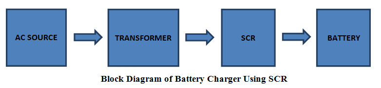
The AC source is given to the step down
transformer which converts the large AC source into limited AC source,
filter the AC voltage and remove the noise and then give that voltage to
the SCR where it will rectify the AC and give the resulting voltage to
the battery for charging.
Circuit Diagram of Battery Charger Using SCR:
Circuit diagram of the Battery Charger Circuit using SCR can be seen below:
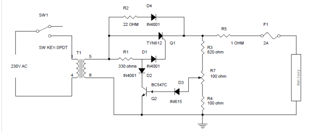
Circuit Diagram Explanation:
- The AC main voltage is given to the step down transformer the voltage should be down to 20V approx. the step down voltage is given to the SCR for rectification and SCR rectifies AC main voltage. This rectified voltage is used to charge battery.
- When the battery connecter to the charging circuit, the battery will not be dead completely and it will get discharged this will give the forward bias voltage to the transistor through the diode D2 and resistor R7 which will get turned on. When the transistor is turned on the SCR will get off.
- When the battery voltage is dropped the forward bias will be decreased and transistor gets turned off. When the transistor is turned off automatically the diode D1 and resistor R3 will get the current to the gate of the SCR, this will triggers the SCR and gets conduct. SCR will rectifies the AC input voltage and give to the battery through Resistor R6.
- This will charge the battery when the voltage drop in the battery decreases the forward bias current also gets increased to the transistor when the battery is completely charged the Transistor Q1 will be again turned on and turned off the SCR.
No comments:
Post a Comment
some simple projects for Electrical&Electronics students