PerfectMoney

Thursday, May 12, 2016

Solar Panel

How Sun Tracking Solar Panel Works?

Ans;-Initially power the circuit.
Place the set up in dark
When the two LDRs are in dark, there is no movement in the panel.
Now place a torch in front of the left LDR. Panels slowly move towards its left.
Now move light from left to right. You can observe the panel moving slowly with the torch towards right.
In the middle, when intensity on both LDRs is equal, panel will not move until there is difference between the light intensity falling on the LDRs.


What The Advantages of Sun Tracking Solar Panel?

Ans:-The solar energy can be reused as it is non renewable resource.
This also saves money as there is no need to pay for energy used.


what the  Applications of Sun Tracking Solar Panel?

Ans:-These panels can be used to power the traffic lights and streetlights
These can be used in home to power the appliances using solar power.
These can be used in industries as more energy can be saved by rotating the panel.
Limitations of Sun Tracking Solar Panel Circuit:

Though solar energy can be utilized to maximum extent this may create problems in rainy season.
Although solar energy can be saved to batteries, they are heavy and occupy more space and required to change time to time.


Monday, February 22, 2016

Duplicate Files Using Duplicate Files Finder

I am always a victim of lots of useless and redundant data in my PC. Out of all these useless files, a good percentage of the content is the duplicate data. It’s always difficult to find duplicate files and delete them manually. So today I am going to show how can you find the duplicate files and delete them from your computer.
There are hundreds of good software out there that can find the duplicate files in your system and remove them. But, I found Duplicate Files Finder light and fast to use. Duplicate Files Finder is a software that locates the duplicate files (same content, but not necessarily same name). You can delete them manually or create links. The search used in this software is very fast compared other programs of the similar nature with hashing algorithms.
Firstly, all the files are sorted by size as duplicate files will have equal size. Other search software use hashing algorithms that scan the files completely. Also, additional caching of files improves the performance.
Take a look at some of its features:
  • Comparison is Byte by byte
  • Search is very fast
  • Support for symbolic links and hardlinks
  • Good interface for deleting files and creating links
  • Variety search options

How To Find Duplicate Files in your system?

Step 1. First you need to download and install the Duplicate File Finder setup in your system. 


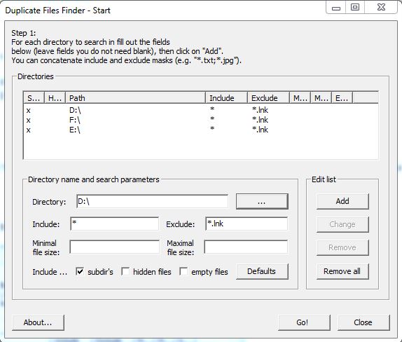
Step 2. Open the Duplicate Files Finder and you will find this app window as shown in image below. Now click the button highlighted in the picture to choose the directory in which you are expecting the duplicate files. Once you selected the directory, click OK.
duplicate-file-finder
Step 3: 
Now click on Add which is located at right-hand side of directory option. Duplicate Files Finder gives you option to add multiple directories or folders at once in which you wishing to find the duplicate files.
selecting-multiple-directories-in-duplicate-file-finder
Step 4. Once you selected all the directories or folders,  Your Duplicate Files Finder will perform a quick search and return the names of duplicate files as well as in which folder they are being stored.
searching -for-duplicate-files
duplicate-file-founded
Now You can delete the duplicate files manually. Have fun using the software.

some simple projects for Electrical&Electronics (EEE)students; for one-stop all electrical students for all electrical information's & projects...

How to use your Android smartphone as remote mouse and keyboard for your PC

Here is how you can control your PC/laptop with your Android smartphone/tablet using it either as keyboard or mouse.

Android OS has increased the overall usage domain of mobile phones in a short period of time. Since it is always fun to do the awesome things with your smartphone, we are presenting a new way to use your Android smartphone/tablet. That is as a keyboard or mouse for your PC.
Before we begin, you must know this “this process will only work with Intel based PCs”. Now first of all you have to get Android Remote Keyboard App and software.
How to Set Up Intel Remote Keyboard
  1. Download Intel Remote Keyboard on your Android device or tablet.
  2. Download and install the Intel Remote Keyboard Host on your Windows PC. You will need to choose x86 or x64 depending on your Windows. If you aren’t sure what you are running, there are four easy ways to know if you’re on 64-bit Windows.
    (Important: Make sure your Android and Windows devices are connected to the same Wi-Fi network.)
  3. On your Android phone, tap the Windows device name.
  4. Your Windows PC will now show a large QR code. Just scan it with your Android smartphone’s camera (following the on-screen instructions) and the two devices will be paired.
  5. You’re all set!
The App is basically a virtual trackpad and keyboard for your computer. You can use it in portrait or landscape mode.
In portrait mode, your screen is divided into the trackpad area on the top and keyboard at the bottom. Intel’s keyboard looks much like any Android keyboard, but also has a Windows button, an Esc button, and the four arrow keys.


Wednesday, February 17, 2016

For Online Resume

Any one want to Good and Quick Resume, Different....


Please Click This Web


 https://www.resyum.com/ 

Tuesday, February 9, 2016

Thermal power station

A thermal power station is a power plant in which heat energy is converted to electric power. In most of the world the prime mover issteam driven. Water is heated, turns into steam and spins a steam turbine which drives an electrical generator. After it passes through the turbine, the steam is condensed in a condenser and recycled to where it was heated; this is known as a Rankine cycle. The greatest variation in the design of thermal power stations is due to the different heat sources, fossil fuel dominates here, although nuclear heat energy and solar heat energy are also used. Some prefer to use the term energy center because such facilities convert forms of heat energy into electrical energy.[1] Certain thermal power plants also are designed to produce heat energy for industrial purposes of district heating, or desalination of water, in addition to generating electrical power. Globally, fossil-fuel power stationsproduce a large part of man-made CO2 emissions to the atmosphere, and efforts to reduce these are varied and widespread.

                  Almost all coal, nuclear, geothermal, solar thermal electric, and waste incineration plants, as well as many natural gas power plants are thermal. Natural gas is frequently combusted in gas turbines as well as boilers. The waste heat from a gas turbine, in the form of hot exhaust gas, can be used to raise steam, by passing this gas through a Heat Recovery Steam Generator (HRSG) the steam is then used to drive a steam turbine in a combined cycle plant that improves overall efficiency. Power plants burning coal, fuel oil, or natural gas are often called fossil-fuel power plants. Some biomass-fueled thermal power plants have appeared also. Non-nuclear thermal power plants, particularly fossil-fueled plants, which do not use co-generation are sometimes referred to as conventional power plants.
Commercial electric utility power stations are usually constructed on a large scale and designed for continuous operation. Virtually all Electric power plants use three-phase electrical generators to produce alternating current (AC) electric power at a frequency of 50 Hz or 60 Hz. Large companies or institutions may have their own power plants to supply heating or electricity to their facilities, especially if steam is created anyway for other purposes. Steam-driven power plants have been used to drive most ships in most of the 20th century until recently. Steam power plants are now only used in large nuclear naval ships. Shipboard power plants usually directly couple the turbine to the ship's propellers through gearboxes. Power plants in such ships also provide steam to smaller turbines driving electric generators to supply electricity. Nuclear marine propulsion is, with few exceptions, used only in naval vessels. There have been many turbo-electric ships in which a steam-driven turbine drives an electric generator which powers an electric motor forpropulsion.
Combined heat and power plants (CH&P plants), often called co-generation plants, produce both electric power and heat for process heat or space heating. Steam and hot water

     The initially developed reciprocating steam engine has been used to produce mechanical power since the 18th Century, with notable improvements being made by James Watt. When the first commercially developed central electrical power stations were established in 1882 at Pearl Street Station in New York and Holborn Viaduct power station in London, reciprocating steam engines were used. The development of the steam turbine in 1884 provided larger and more efficient machine designs for central generating stations. By 1892 the turbine was considered a better alternative to reciprocating engines;[2] turbines offered higher speeds, more compact machinery, and stable speed regulation allowing for parallel synchronous operation of generators on a common bus. After about 1905, turbines entirely replaced reciprocating engines in large central power stations.


The largest reciprocating engine-generator sets ever built were completed in 1901 for the Manhattan Elevated Railway. Each of seventeen units weighed about 500 tons and was rated 6000 kilowatts; a contemporary turbine set of similar rating would have weighed about 20% as much

The energy efficiency of a conventional thermal power station, considered salable energy produced as a percent of the heating value of the fuel consumed, is typically 33% to 48%.[citation needed][4] As with all heat engines, their efficiency is limited, and governed by the laws of thermodynamics. By comparison, most hydropower stations in the United States are about 90 percent efficient in converting the energy of falling water into electricity.[5]
The energy of a thermal not utilized in power production must leave the plant in the form of heat to the environment. This waste heat can go through a condenser and be disposed of with cooling water or in cooling towers. If the waste heat is instead utilized for district heating, it is called co-generation. An important class of thermal power station are associated with desalination facilities; these are typically found in desert countries with large supplies of natural gasand in these plants, freshwater production and electricity are equally important co-products.
The Carnot efficiency dictates that higher efficiencies can be attained by increasing the temperature of the steam. Sub-critical fossil fuel power plants can achieve 36–40% efficiency. Super critical designs have efficiencies in the low to mid 40% range, with new "ultra critical" designs using pressures of 4400 psi (30.3 MPa) and multiple stage reheat reaching about 48% efficiency. Above the critical point for water of 705 °F (374 °C) and 3212 psi (22.06 MPa), there is no phase transition from water to steam, but only a gradual decrease in density.
Currently most of the nuclear power plants must operate below the temperatures and pressures that coal-fired plants do, in order to provide more conservative safety margins within the systems that remove heat from the nuclear fuel rods. This, in turn, limits their thermodynamic efficiency to 30–32%. Some advanced reactor designs being studied, such as the very high temperature reactor, advanced gas-cooled reactor and supercritical water reactor, would operate at temperatures and pressures similar to current coal plants, producing comparable thermodynamic efficiency.

The direct cost of electric energy produced by a thermal power station is the result of cost of fuel, capital cost for the plant, operator labour, maintenance, and such factors as ash handling and disposal. Indirect, social or environmental costs such as the economic value of environmental impacts, or environmental and health effects of the complete fuel cycle and plant decommissioning, are not usually assigned to generation costs for thermal stations in utility practice, but may form part of an environmental impact assessment.
Typical diagram of a coal-fired thermal power station
1. Cooling tower10. Steam Control valve19. Superheater
2. Cooling water pump11. High pressure steam turbine20. Forced draught (draft) fan
3. Transmission line (3-phase)12. Deaerator21. Reheater
4. Step-up transformer (3-phase)13. Feedwater heater22. Combustion air intake
5. Electrical generator (3-phase)14. Coal conveyor23. Economiser
6. Low pressure steam turbine15. Coal hopper24. Air preheater
7. Condensate pump16. Coal pulverizer25. Precipitator
8. Surface condenser17. Boiler steam drum26. Induced draught (draft) fan
9. Intermediate pressure steam turbine18. Bottom ash hopper27. Flue-gas stack

Monday, February 8, 2016

Justdial/Customer service


for information throw to the phone in min...

Just dail


088888 88888

Mca21 - Ministry Of Corporate Affairs


For Searching company in india.....

click this web


http://www.mca.gov.in/DCAPortalWeb/dca/MyMCALogin.do?method=setDefaultProperty&mode=16

Wednesday, January 27, 2016

Solar panel

The non renewable energy resources are decreasing, use of renewable resources for producing electricity is increasing. Solar panels are becoming more popular day by day. Solar panel absorbs the energy from the Sun and is stored in the battery. This energy can be utilized when required. Utilization of the energy stored in batteries is mentioned in below given applications. Solar panels should absorb energy to a maximum extent. This can be done only if the panels are continuously placed towards Sun direction. So solar panel should continuously rotate in the direction of Sun. This article describes about circuit that rotates solar panel.

Principle of Sun Tracking Solar Panel 

The Sun tracking solar panel consists of two LDRs, solar panel and stepper motor and ATMEGA8 Micro controller.
Two light dependent resistors are arranged on the edges of the solar panel. Light dependent resistors produce low resistance when light falls on them. The stepper motor connected to the panel rotates the panel in the direction of Sun. Panel is arranged in such a way that light on two LDRs is compared and panel is rotated towards LDR which have high intensity i.e. low resistance compared to other. Stepper motor rotates the panel at certain angle.
When the intensity of the light falling on right LDR is more, panel slowly moves towards right and if intensity on the left LDR is more, panel slowly moves towards left. In the noon time, Sun is ahead and intensity of light on both the panels is same. In such cases, panel is constant and there is no rotation.
Components in the Circuit:
  • Solar panel
  • ATmega8 micro controller
  • Light Dependent Resistor.
  • Motor driver IC
  • Stepper Motor.

Automated Sun Tracking Solar Panel Circuit Design:

The proposed system consists of ATmega8 micro controller, Solar panel, Light Dependent resistors and motor driver IC.
ATmega8 is AVR family micro controller. It is based on advanced RISC architecture. It is an 8 bit controller. It has 4KB Flash memory, 512 bytes of EEPROM and 1Kb of SRAM. It has 23 programmable pins. It supports peripheral features like two 8-bit timers, one 16 bit timer, 6 channel ADC with 10-bit resolution, programmable USART, Serial peripheral interface, 2 wire serial interface, etc.
Solar panel is connected to Stepper motor. Solar panel consists of photovoltaic cells arranged in an order. Photovoltaic cell is nothing but a solar cell. Photo resembles light and voltaic is electricity. Solar cell is made up of semiconductor material silicon. When a light ray from Sun is incident on the solar cell, some amount of energy is absorbed by this material. The absorbed energy is enough for the electrons to jump from one orbit to other inside the atom. Cells have one or more electric field that directs the electrons which creates current. By placing metal contact energy can be obtained from these cells.
Light Dependent Resistors are the resistors whose resistance values depend on intensity of the light. As the intensity of light falling on the LDR increases, resistance value decreases. In dark, LDR will have maximum resistance. LDR will output an analog value which should be converted to digital. This can be done using analog to digital converter. ATmega8 has analog to digital converter internally. It has six ADC channels from ADC0 to ADC5.The two LDRs are connected to ADC pins i.e. PC0 and PC1. ADC conversion is done using successive approximation method.
Stepper motor rotates the panel in a stepwise angle. To drive this motor a driver IC is used. Driver IC amplifies the input voltage and protects the microcontroller from back EMF. Generally, motors generate back EMF. This may damage the controller. The driver IC used is L293D. It has H bridge internally made up of transistors. This IC has 16 pins. Output pins are connected to the stepper motor pins. Input pins are connected to the controller pins as shown in circuit diagram.
By connecting a battery to the solar panel, one can store the energy generated by the solar cells and this energy can be used when required.


some simple projects for Electrical&Electronics(EEE) students; for one-stop all electrical students for all electrical information's & projects...

Saturday, January 23, 2016

Grounding Transformer or Earthing Transformer

transformer on the Delta Side is outsides the Zone of protection the Earth
Fault(E/F)in the delta system outside Current Transformer(CT)
locations would produce current distributions as shown
which circulate within the differential CT secondaries and is kept out of
operating coils.

Zig-Zag
or inter connected star grounding transformer has
normal magnetising impedance of high value but for E/F, currents flow in
windings of the same - core in such a manner that the ampere turn cancel and
hence offer lower impedance.

In
cases where the neutral point of three phase system is not
accessible like the system connected to the delta connected side of a electrical power
transformer, an artificial neutral point may be created with help of a
zigzag connected earthing transformer.

zigzag star connected earthing transformer
This is
a core type transformer with three limbs. Every phase winding in zigzag
connection is divided into two equal halves. One half of which is wound on one
limb and other half is wound on another limb of the core of transformer.

1st
half of Red phase winding is wound on the 1st limb of the core and 2nd half of
same Red phase is wound on 3rd limb.

1st
half of Yellow phase winding is wound on the 2nd limb of the core and 2nd half
of same Yellow phase is wound on 1st limb.

1st
half of Blue phase winding is wound on the 3rd limb of the core and 2nd half of
same Blue phase is wound on 2nd limb.

End point of all three winding ultimately
connected together and forms a common neutral point. Now if any fault occurs at
any of the phases in delta connected system, the zero sequence fault current has close path of
circulating through earth as shown in the figure.


In
normal condition of the system, the voltage across the winding of
the earthing transformer is 1/√3 times of rated per phase voltage of the
system. But when single line to ground fault occurs on any phase of the system,
as shown in the figure, zero sequence component of the earth fault current flows
in the earth and returns to the electrical power system
by way of earth star point of the earthing
transformer. It gets divided equally in all the three phases. Hence, as
shown in the figure, the currents in the two different halves of two windings
in the same limb of the core flow in opposite directions.

earthing transformer
And
therefore the magnetic flux set up
by these two currents will oppose and neutralize each other. As there is no
increase in flux due to fault current, there is no change of dφ/dt means no
concluded like that, the zigzag type earthing or grounding
choking effect occurs to impede the flow of fault current. So it can be
transformer maintains the rated supply voltage at normal current as
well as when a solid single line to ground fault current flows
through it.

The
rated voltage of an
earthing or grounding transformer is the line to line voltage on
which it is intended to be used. Current rating of this transformer is the
maximum neutral current in
Amperes that the transformer is designed to carry in fault condition for a
specific time. Generally the time interval, for which transformer designed to
carry the maximum fault current
through it safely, is taken as 30 second.