Have you ever tried to design a variable
regulated power supply? This article describes you how to design a
variable power supply circuit which will provide 0 to 28V at 6 to 8
amps. Till now we have seen a lot of power supply circuits, but the main
advantage of this power supply circuit is that it provides almost 2 to 3
times high current than the normal power supply circuits. Even we can
use this design to produce a current of 20 amps with little modification
(use proper rating transformer and a huge heat sink with fan). Huge
heat sink is required in this circuit, as 2N3055 transistors produce
very heat at full loa
 Circuit Components:
Pot RV2 is used to set the maximum current available at the output. If you use a 100 ohm/1 watt potentiometer then the output current is limited 3 Amps at 47 ohms and 1 Amp at 100 ohm.
d.
0-28V, 6-8A Power Supply Circuit Diagram using LM317 and 2N3055:
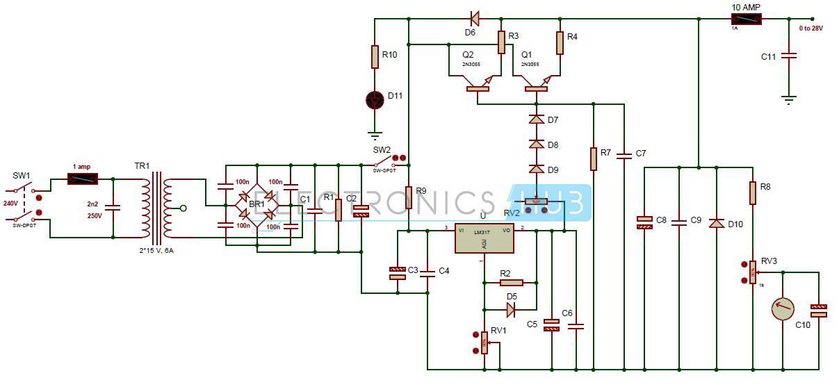
0-28V, 6-8A Power Supply Circuit Diagram using LM317 and 2N3055
- 30V, 6A Step down Transformer
- Bridge diodes (four) – MR750
- Fuse F1 – 1 Amp
- Fuse F2 – 10 Amp
- Resistor R1 (2.5 watt) – 2.2k ohm
- Resistor R2 – 240 ohm
- Resistor R3, R4 (10 watt) – 0.1 ohm
- Resistor R7 – 6.8k ohm
- Resistor R8 – 10k ohm
- Resistor R9 (0.5 watt) – 47 ohm
- Resistor R10 – 8.2K
- Capacitors C1, C7, C9 – 47nF
- Electrolytic capacitor C2 – 4700uF/50v
- C3, C5 – 10uF/50v
- C4, C6 – 100nF
- C8 – 330uF/50v
- C10 – 1uF/16v
- Diode D5 – 1n4148 or 1n4448 or 1n4151
- D6 – 1N4001
- D10 – 1N5401
- D11 – LED red
- D7, D8, D9 – 1N4001
- LM317 adjustable voltage regulator
- 2N3055 transistors – 2
- heat sink
- Pot RV1 – 5k
- Pot RV2 – 47 ohm or 220 ohm, 1 watt
- Pot RV3 – 10k trimmer
0-28V, 6-8A Power Supply Circuit Design:
Although the voltage regulator LM317 protects the circuit from overheating and overload the Fuses F1 and F2 are used to protect the power supply circuit. The rectified voltage at capacitor C1 is around 42.30V (30 volt *SQR2 = 30v *1.41 =42.30). So we need to use all the capacitors which are rated at 50v in the circuit. Pot RV1 allows us to vary the output voltage in between 0 to 28V. The minimum output voltage of LM317 voltage regulator 1.2V. In order to get 0V at the output we are using 3 diodes D7, D8 and D9. Here 2N3055 transistors are used to get more current.Pot RV2 is used to set the maximum current available at the output. If you use a 100 ohm/1 watt potentiometer then the output current is limited 3 Amps at 47 ohms and 1 Amp at 100 ohm.
LM317 Voltage Regulator:
LM317 is the 3 pin series adjustable voltage regulator. This regulator provides output voltage ranging from 1.2V to 37V at 1.5 amps. This IC is easy to use and requires only two resistors to provide the variable supply. It provides internal current limiting, thermal shut down and it provides more line and load regulation as compared to fixed voltage regulators. Because of all these features these IC is mostly used in variety of applications.How to Operate 0-28V, 6-8A Power Supply Circuit Design:
- Firstly give the connections as per the circuit diagram
- While giving the connections, make sure that there is no common connection between AC and DC supply.
- Connect digital multi meter at the output terminals of the circuit.
- Switch on the DPST switch.
- Now adjust the pot RV1 and check the voltage in multimeter. Now you can observe vary in voltage. You will get the voltage in between 0 to 28V.
- Vary the output current by varying Pot RV2.
- Switch off the DPST switch.
0-28V, 6-8A Power Supply Circuit Advantages:
- The circuit provides variable supply. For variable power supply circuits, read the post – Variable Voltage Power Supply from Fixed Voltage Regulator
- This circuit provides high output current than the normal power supply circuits
0-28V, 6-8A Power Supply Circuit Applications:
- Used in various power amplifiers and oscillators to provide DC supply.
- This circuit is used in appliances
- Used as RPS (Regulated power supply) to provide the DC supply to the various electronic circuits.
Circuit Limitations:
This circuit is studied theoretically and may require some changes to implement it in practical.d.
No comments:
Post a Comment
some simple projects for Electrical&Electronics students