The polarity of lots of components viz diodes, LED comprises Zener diode
as well as infrared LED can be tested with the help of very simple
circuit named Polarity cum Continuity Tester. With the
help of this circuit, we can also identify that whether the components
we are using in our circuit are good or bad before mounting them on the
PCB. Although it happens many times that people are not being able to
discovered the polarity of any component and mount them wrong in the
circuit which leads to damage of the component or may damage the
entire circuit. The content of any circuit can also be tested with the
help of this circuit, i.e. it also works as a Continuity Tester

Polarity Cum Continuity Tester Circuit Diagram:
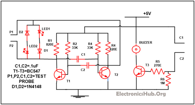
Continuity Tester Circuit Diagram – ElectronicsHub.Org
Components Used in this Circuit:
- Resistor:It is a passive component and mainly employed in the circuit to direct the flow of current in the circuit. Resistors are broadly classified as fixed type and variable type.
- R1, R4 (820E) – 2
- R2, R3 (33K) – 2
- R5 (270E) – 1
- R6 (1M) – 1
- D1, D2 (1N4148) – 2: It is a semiconductor device and it permit the current to flow merely in forward direction and block the current in backward direction.
- LED1, LED2 – 2: LED is a semiconductor device and generally work as an indicator in any circuit and works on low voltage and current.
- C1, C2 (. 1uF) – 2: Capacitors are mainly employed in the circuit to store the charges. A dielectric medium flows in it which is used to separate the two conducting plates inside it.
- T1-T3 (BC548) – 3: Transistor is a semiconductor device mainly used to amplify the current.
- Buzzer – 1: Also known as beeper and is an audio signal device
Polarity Cum Continuity Tester Circuit Description:
Firstly in any manner connects the
component which you want to test with test probe. Glowing of any LED in
this circuit is the indicator of cathode terminal. Both the LED in the
circuit will start glowing when you first start the circuit. Now across
the probe provide for testing connect the component. If LED1 start
glowing it means that the cathode side of the component is coupled to
the probe 1 and if LED2 start glowing it implies that the cathode side
of the component is coupled with probe 2.
The circuit is finished with the aid of
two transistors and both the transistors in the circuit are connected as
an astable multivibrator. The circuit output which we get from the both
transistors are not in phase with one another, it implies that if we
get high output from the first transistor then the other transistor
output will be low or if the output of the second transistor is higher
than the output from the first transistor will be low. LED 1 will start
glowing when T1 transistor is in “on” state and T2 transistor is in
“off” state. In the same manner LED 2 will be glowing when the T1
transistor is in the “off” state while T2 transistor is in “on” state.
When the component like diode or LED
which you want to test is put between the probes provided for testing it
bypasses to any one of the LED based on the polarity.In place of the
bypass LED the test current will start flowing via a component in the
circuit. Series grouping of LED as well as diodes are connected in the
circuit with the T1 and T2 transistor at the collector terminal so that
it can raise the forward voltage drop.This will make sure that the
voltage drop across any one of the LED is bigger as compared with the
forward drop of the component being examined.
The result of the test when the component is connected-
- If LED 1 starts glowing this implies that at probe 1 of the tester cathode is coupled while at probe 2 of the tester anode is coupled.
- If LED2 starts glowing it implies that at probe 1 of the tester anode is coupled while cathode of the component is coupled with probe 2.
- If any of the LED will not glow it implies that the component coupled to the circuit is short circuit and due to that stable multivibrator of the circuit stop oscillating
- If the components open circuit than both the LED in the circuit will start glowing.
If you want to check the continuity of
the circuit coupled the circuit with the polarity cum continuity tester
circuit with the help of probe C1 and C2 provided in the circuit. A
sound of the buzzer will start when both the probes are attached to each
other it means that your circuit is in proper working condition. When
probe C1 and C2 are not connected with each other than at that time
transistor T3 is closed and there is no base current. At this moment
voltage level of transistor T3 at the emitter and base are of the same
level. Transistor gotten open at the time when you start the continuity
test and as compared with the emitter base of the transistor is at a
higher level so the sound started from the buzzer connected with it.
Different types of cables and PCB can be checked with the help of this
circuit.
No comments:
Post a Comment
some simple projects for Electrical&Electronics students