A sound card is a device which allows the computer or an embedded system to create and record real and high quality sound. It is used to translate analog sound signal into computer recognized digital signal and vice-versa. Typical sound card consists of an analog to digital converter to convert analog sound signal to digital signal and a digital to analog converter to convert the digital signal to sound signal. In other words it allows the user to record and play sound. Its benefits are it is small and portable, can be easily installed and helps to increase sound capabilities of a computer.Though sound cards are available internally inside a computer’s mother board, some cards can be used externally. These are known as USB sound cards. They can be a simple pen drive type device consisting of a microphone and headphone jacks. It usually consists of internal circuitry which transmits and receives digital data from computer and deciphers the data. In simple words, it translates sound signals into computer recognized digital data and vice-versa.

USB Sound Card Circuit Working Principle:
Usually sound signal is received from microphone, converted to the electric signal and fed to the sound card which consists of internal circuit to amplify and encode the analog signal to digital signal. These encoded digital bits are transmitted through the USB channel to the computer. In the similar way, when digital bits are received from the computer through the USB channel, the sound card decodes the digital bits into analog electric signal. This electric signal is converted to sound signal by the speaker.
In plain words, USB sound card allows user to record and play music externally.
USB Sound Card Circuit Diagram:
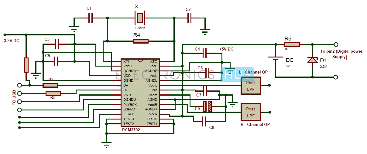
USB Sound Card Circuit Diagram
USB Sound Card Circuit Design:
A USB sound card circuit can be designed using a 16 bit digital to analog converter PCM2702. It consists of two D/A output channels and USB 1.0 compatible integrated interface controller. It can accept sampling data rates of 48KHz, 44.1KHz and 32KHz. USB port is connected to the IC through the 4 pins D+, D-, Vbus and DGNDU.
The decoded audio signal is available at the VOUTL and VOUTR pins. The IC uses two power supplies – +3.3V Digital Power supply and +5V Analog power supply.
Here we use external power supply to power up the device. Here we use a simple battery to obtain the 5V supply and a Zener diode to provide a constant voltage source. Here we use Zener diode 1N4728 to provide 3.3V supply through the input supply of 5V. Keeping in view of requirement of maximum amount of 1A to flow in the Zener reference circuit , we can obtain the voltage equation as given below:
Vin –(R*Im)+Vout = 0
or
(Vin + Vout)/Im = R
Substituting the values of Vin as 5V, Vout as 3.3V and Im as 1A, we get the value of R to be 8.3Ohms. Here we select a resistor of 10 Ohms.
Other crucial design parts involve using a crystal oscillator of 12MHz connected between pins 1 and 28 along with a 1MOhm resistor and two capacitors of 33pF each. This is used to provide clock signal to the IC for USB and audio functions.
The 5V power supply is given to power the device, the PLL section and the output channels whereas the 3.3V power supply is given to power the USB and the clock generator. USB is connected to the device at pins 6,7 ,8 and 9 whereas the output is available at pins 19 and 23.
How to Operate USB Sound Card Circuit?
Operation of PCM2702 is based upon the process of USB communication. Here PCM2702 is the USB device whereas a computer or a laptop is the host. The IC consists of two endpoints supporting control and isynchronous data transfer. If one can recall, endpoints refer to the points on USB device where simplex communication takes place. Once the circuit is connected to the host (a computer or a laptop), the device software installed in the Computer initiates the communication. A token packet is sent to the device consisting of request query.
Remember data or information is sent across USB in form of packets. Each packet consists of packet identification data bits, address bits and endpoints field. The device then sends an acknowledgement packet to indicate the connection is successful.
Once the connection is established, the analog outputs are set to bipolar zero. The device then receives the audio data and stores it in its internal buffer memory. The digital to analog converter then converts this digital data into analog signal. PCM2702 plays this audio data once the device receives state of frame bit. Here we have connected a LED to the pin 10 such that when PCM2702 plays the audio data, this pin is at low logic signal, thus allowing the PNP transistor to conduct. This provides a forward bias to the LED and it starts conducting, thus emitting light to indicate the device is playing audio.
USB Sound Card Circuit Applications:
- It can be used as in home theater system.
- It can be used in replacement for internal sound card.
- It can be used as a record and play device.
- It can be used in surrounding sound system.
Limitations of the Circuit:
- This is just a theoretical circuit and in practical implementation requires designing of audio amplifier circuits to drive speakers or headphones.
- Use of Zener diode doesn’t guarantees accurate output voltage of 3.3 V.
No comments:
Post a Comment
some simple projects for Electrical&Electronics students