Human detection robot is not a new technology. Many types of human detection robots were designed depending on the application. During the natural calamities like earthquakes, it is difficult to rescue the human beings under the buildings. Though detection by rescue team is done, it consumes a lot of time. Detection of human in appropriate time is very important in such situations. This article presents a simple human detection robot that is operated manually using RF technology


Human Detection Robot Circuit Principle:
The main principle of the circuit is to detect the human using human detection sensor. The wireless robot is operated manually using PC. The wireless technology used here is Radio Frequency technology. The data is transmitted to receiver through RF. Using the received data, robot is operated and controlled.
Human Detection Robot Circuit Diagram:
Transmitter Circuit:
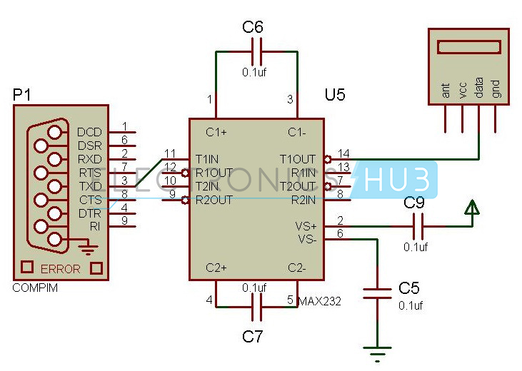
Human Detection Robot Circuit Diagram – Transmitter Section
Receiver Circuit:
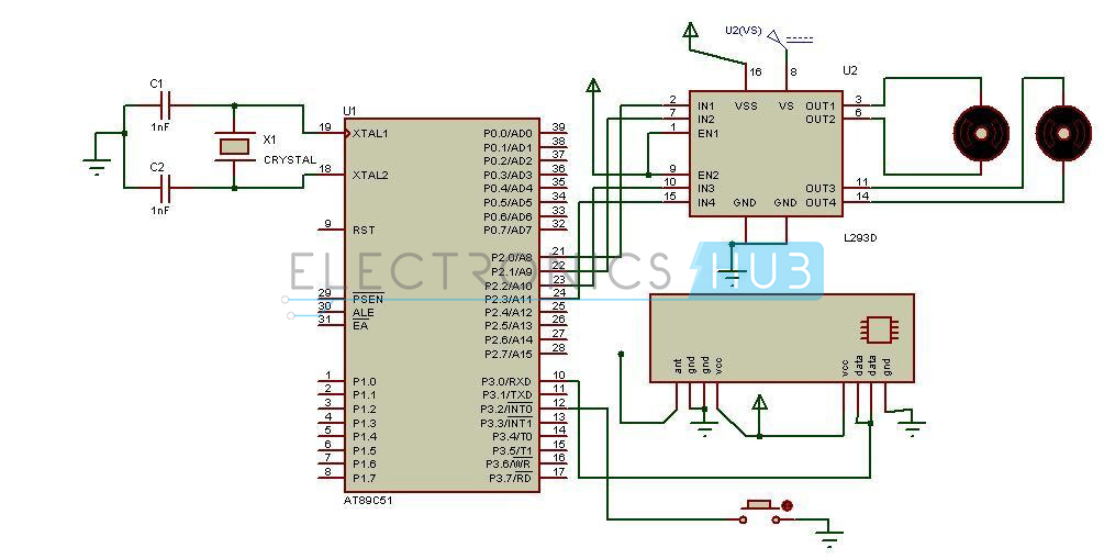
Human Detection Robot Circuit Diagram – Receiver Section
Circuit Components:
- AT89s51 microcontroller.
- PIR sensor.
- RF transmitter and receiver.
- L293D IC.
- PC.
- Robot chassis.
- Max232 IC.
- 9V battery.
- Motors.
Human Detection Robot Design:
The circuit can be divided into two sections 1) Transmitter Section, 2) Receiver Section.
Transmitter Section:
The transmitter section consists of PC, RF transmitter, MAX232IC, DB9 connector. The commands for operating the robots are transmitted using Personal computer. PC transmits the data to the RF transmitter through max232.
Max232 converts the logic levels. The logic levels of PC are in the range ± 3v to ± 15V, while the logic levels of RF module is compatible with TTL.In order to convert this voltage MAX 232 is used .This is also called level converter .The T1in pin of the MAX232 is connected to the receive pin of the DB9 which is in turn connected to the PC. The output pins are connected to the RF transmitter.
Radio frequency is the wireless technology used here to transmit the data .Several carrier frequencies were used in available modules such as 433.92 MHZ,315MHZ ,868MHZ,915MHZ,2400MHZ .Here the RF modules uses a frequency of 433 MHZ. The DATA pin of the RF transmitter is connected to the T1out of the MAX232.A Vcc of 5v is applied to the RF transmitter.
Receiver Section:
The receiver section consists of AT89c51microcontroller, L293D motor driver IC, RF receiver, motors of the robot, PIR sensor.
AT89c51 is an 8051 family microcontroller. It is an 8-bit microcontroller. It has 40pins.It has flash memory of 4K bytes.
The RF receiver module is connected to the port3 of the microcontroller. Data pins of RF receiver are connected to the receiver pin of the microcontroller. The two Vcc pins are shorted and connected to a supply of 5v.GND pins are shorted and connected to ground. The receiver module receives the data and transmits it to the microcontroller.
PIR sensor plays a main role in the circuit. This is used to detect the human beings. The PIR sensor is nothing but Passive Infra Red sensor. These sensors work on the principle that they every human being emits infra red radiations of very low wave length. Thus this sensor senses these radiations and outputs a logic high value. This sensor can sense the human within the range of 20feet. They have an operating voltage of 2.2-5V. PIR sensor is connected to the Port1 of the micro controller.
L293D is a motor drive IC. This IC is required to drive the motor and also eliminates back EMF generated. This IC internally has H-bridge circuit. This has 16 pins out of which four input pins are used to drive two motors. Enables are used to enable these input pins. A supply voltage of 5v is applied at the 16th pin to operate the IC.8th pin is applied with a voltage of 12v required to drive the motors. The L293D IC can drive voltages up to 36v.That is 8th pin can be applied with a voltage ranging from 2.4v to 36v.
How Human Detection Robot Works?
- Initially burn the code into the micro controller.
- Arrange the robot chassis.
- Connect the transmitter and receiver circuits as shown in the circuit diagram.
- Now arrange the transmitter to the robot.
- Connect the receiver to the PC.
- Enter the character F in the hyper terminal of the PC.
- This makes the robot to move in forward direction.
- Now enter the character B to move the robot in reverse direction.
- Enter L and R to move the robot in left and right directions.
- While the robot is moving if any human detected by the PIR sensor robot stops moving and a buzzer is switched on.
Human Detection Robot Applications:
Following are the main applications of this Human Detection Robot.
- Human detection robot can be used at the time of natural calamities to save the lives of human.
- This can also be used to detect the humans in the war field.
- This can be used for security purpose in the jewellery shops, museums, etc.
Limitations of the Circuit:
- The PIR sensor cannot detect human out of its range
No comments:
Post a Comment
some simple projects for Electrical&Electronics students