Generally, one can see the digital displays which display the score when buttons are pressed on score boards. The main heart of this score board is 2 digits up/down counter circuit. The 2 digits are displayed on two 7 segment displays. This article describes 2 digit up/down counter circuit.
2 Digit Up/Down Counter Circuit Principle:
The main principle of this circuit is to increment the values on seven segment displays by pressing the button. When button 1 is pressed value on the display is incremented by one value and when other button is pressed value on the display is decremented by one value. The value on the display can be incremented and decremented from 0-99 as it uses only 2 displays. If one wants to display 3 digits, three displays should be used .There are many circuits available for 2 digit up/down counter but using a microcontroller reduces components and space on the board but simple programming is required.
Also Read the Related Post – Frequency Counter Circuit
Two Digit Up/Down Counter Circuit Diagram:
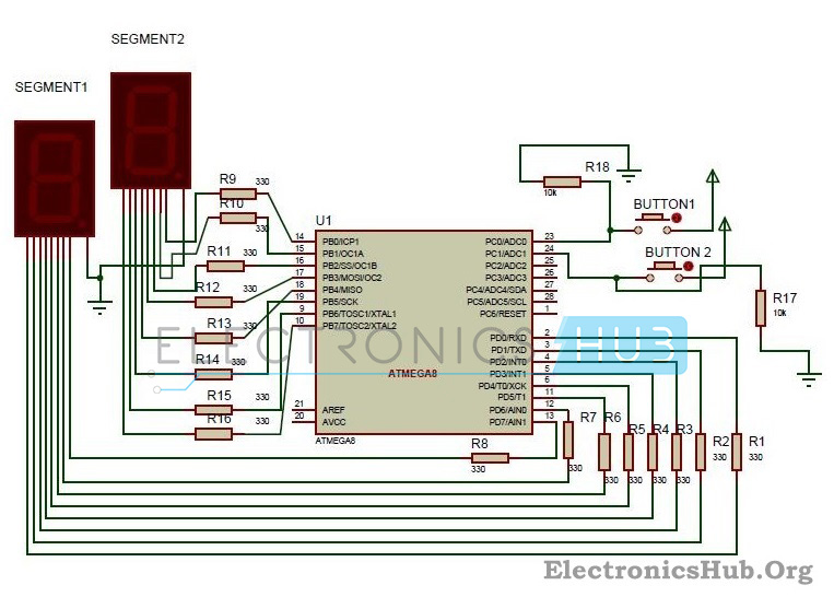
2 Digit Up Down Counter Circuit Diagram
Circuit Components:
- ATMEGA8 Microcontroller
- Seven segment displays(common cathode) – 2
- Resistors – 18 (R1 to R18)
Circuit Design of 2 Digit 7-Segment Up/Down Counter:
The 2digit Up/Down counter consists of two seven segment displays connected to ATMEGA8 microcontroller. The seven segment display consists of 8 pins and one common pin.
There are mainly two types of seven segment displays 1) common cathode 2) common anode. The display here used is common cathode display. Generally for common cathode displays, common pin should be grounded and for common anode, it should be connected to VCC. In, Seven segment display, there are seven segments and they are similar to seven LEDs. Seven pins belong to these seven segments where as the last pin is dot at the coner of the display. For common cathode, display assigning logic1 to the segment pin glows particular segment. In case of common anode, the segment pin should be assigned logic0 in order to glow the segment. Each segment is given one name starting from ‘a ‘and last segment dot is ‘h’.
In our circuit, seven segment display is connected to micro controller through a current limiting resistor of 330 ohms. Two buttons in pull- down mode are also connected.
The necessity of connecting the buttons in pull down mode is to avoid floating state of the button i.e. unknown state. If the button is connected in pull down mode, this ensures that button is initially in logic0 state.
How to Operate 2 Digit Up/Down Counter Circuit?
- Initially, power the circuit.
- The values displaying on seven segments is ‘00’.
- Press the button 1 in the circuit. The value on the seven segments is incremented to ‘01’.
- Again press button 1. Value on the displays is ’02’.
- Now, press the second button. You can see the value decrementing to 01.
- The value on the displays can be incremented up to 99, after 99 if button 1 is pressed it starts incrementing from ‘01’. If the second button is pressed after decrementing to ‘00’, it displays ‘00’. This value can be changed only after incrementing the value atleast to ‘01’.
Algorithm for Programming:
- Declare Port D, Port B as outputs and Port C as input.
- Declare two arrays with the seven segment codes.i.e if number one is to be displayed the binary value that should be passed is as follows:
h g f e d c b a
0 0 1 1 0 0 0 0
0 0 1 1 0 0 0 0
This is because e and f segments should be assigned with logic 1 to display ‘1’. So binary value 0b00110000 is assigned to the particular port on which ‘1’ is to be displayed. Each array should consist of 0-9 binary values.
- Check the status of the buttons using if else loop.
- If the button 1 is pressed for first time, segment 1 should display 0 and segment 2 should display 1. So the output is ‘01’.
- If the button 1 is pressed for second time, value on second button should be incremented by one.
- If the second button is pressed, value on the first segment should be decremented by one value.
2 Digit Up/Down Counter Circuit Applications:
- This circuit can be used in scoreboards.
- Up/down counter is used for counting number of objects passed through a point.
- It is used to count number of persons entering a room.
Limitations of this Circuit:
This particular Up/Down Counter circuit is limited to 2 digits i.e. 0-99. If more than 3 digits are required, one should use another display which requires more pins from the controller.
Note:
If you are interested to get code, kindly take some time and answer following questions in the comment section, so that we will send you the code.
- Why you need this project code?
- Are you trying to make the same project or different one?
- Give us more details about your project.
No comments:
Post a Comment
some simple projects for Electrical&Electronics students