A frequency counter is an instrument used to measure the frequency. In scientific terms, frequency is the number of cycles per second in the signal. In terms of a layman, frequency of a signal denotes the rate of occurrence of the signal in certain time. Frequency Counters are basically simple counter systems with a limited time period for counting.
Frequency Counter Circuit Operating Principle:
This circuit is based on the simple definition of frequency, which is the number of cycles per second. An astable multivibrator is used to generate oscillating pulses which are fed as clock pulses to a counter. Another monostable multivibrator is used to generate a timing signal for 1 second used to control the counter. The counter thus counts the number of pulses for 1 second and the resultant value displayed on the 7-segment display is the value of frequency in hertz.
Frequency Counter Circuit Diagram:
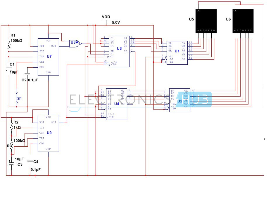
Circuit Diagram of Frequency Counter
Frequency Counter Circuit Design:
The primary requirement in our circuit is to generate an oscillating signal with a duty cycle of about 99% such that the time low value is less than the time high value of the output signal. Since duty cycle depends only on the value of the threshold and discharge resistors, it can be adjusted by selecting the proper values of resistors.
The duty cycle is given by D = (Ra+Rb)/(Ra+2Rb)
Substituting the value of D to be 0.99, we get the value of Ra to be 98 times the value of Rb. Thus selecting a value of 100 Ohms for Rb and 9.8k for Ra. Practically the value of 10k is chosen for Ra.
Another requirement is to design a monostable multivibrator using 555 Timer. This circuit is designed to generate an output signal for duration of 1 sec. Since the time period of the output signal is equal to 1.1 times the product of R and C, (where R is the resistor between the discharge and Vcc pins, C is the capacitance between discharge pin and ground). Selecting a value of 100K for R, we calculate C to be about 9.09uF. Here we select 100K resistor and a 10uF capacitor.
Next step of designing is the design of the counter circuit. Here our requirement is the measurement of frequency till 99Hz. We achieve this by synchronous cascading of two counter ICs – 4510. The clock pin of both ICs are connected to the output of the Timer 1 and the carry out pin of IC1 is connected to the carry in pin of IC 2. Since ICs 4510 do not have any in built display decoder, we require display decoder IC – CD4511 for each IC. The output pins of both decoder ICs are connected to the 7 segment display.
Since our other requirement is to count the number of pulses for one second, we have to design a combinational circuit using another NAND gate whose inputs are connected to the output pin of Timer2 and Vcc. The output signal is connected to the reset pin of the counter IC1.
Do you about the concept – Bi Directional Visitor Counter using 8051 Microcontroller
Frequency Counter Circuit Operation:
The circuit commences to operate once switch S1 is in closed position. Based on the selected value of electrolyte capacitor, the 555 Timer produces an output signal whose frequency depends upon the value of the capacitor. This signal is fed as clock signal to the counter IC1. As long as reset pin of counter IC is at low logic low the counter will proceed it’s counting. This is turn depends upon the time for which the reset pin is held at logic low level. Since the output pin of NOR gate IC is connected to the reset pin of IC1, a logic high signal at one of the inputs ensures a low signal at the reset pin. In other words, as long as the Timer1 generates a high output signal, the reset pin continues to be at low logic level and the counter continues its operation. However in case the count value reaches 9, the second counter comes into action and increases its count by 1. This whole process repeats until the Timer1 stops generating signal after a set time period and the output of the NOR gate is at logic high level, thus causing the counter IC1 to reset. The counts are displayed on the 7 segment displays connected directly to the counter ICs. The value of the count displayed shows the approximate count of number of cycles per second or frequency of the output signal.
Limitations of this Circuit:
- This circuit takes into account the signals with high duty cycle such that timing value of negative pulse is quite low compared to that of the positive pulse. This in turn can be erroneous.
- This circuit uses CMOS devices which are quite static and cannot be used with bare hands.
- This circuit is not accurate.
No comments:
Post a Comment
some simple projects for Electrical&Electronics students