A stun gun is a gadget used to produce a high voltage, low current signal, used mostly as a weapon to stun or send shock waves to the target with the intention to weaken or paralyze it. However proceeding to design the circuit, it should be kept in mind that in some countries, stun gun is banned. Because, this is actually a lethal weapon which can render a person mentally paralyzed. It is usually powered by a 9V battery. Here, we design a stun gun circuit using a 555 Timer to produce a current fluctuating signal and a voltage multiplier using a transformer and a multiple stage arrangement of voltage doublers using capacitors and diodes.
Stun Gun Circuit Operating Principle:
The stun gun circuit is based on the principle behind a conventional stun gun. A 555 Timer is used to produce an oscillating signal of frequency determined by the external passive elements connected to the Timer. These low current electric pulses are fed to a step up transformer to produce a high volt signal, which is further increased by a voltage multiplier circuit. The voltage multiplier circuit consists of multiple stages of voltage doubler each consisting of two diodes and two capacitors. The voltage doubler circuits are based on Villard doubler method. Output voltage is directly proportional to the number of stages.
Stun Gun Circuit Diagram:
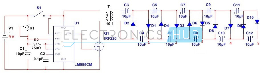
Circuit Diagram of Stun Gun
Stun Gun Circuit Design:
Actually, here we require two phases of designing – The astable multivibrator design and voltage multiplier design.
Designing the circuit requires pioneer step of deciding the output voltage . Here our requirement is to generate a 10KV DC voltage from 1000V input.
From the equation,
Vout = (2Vin + 1.414)S, where S is the number of stages.
To obtain voltage of 10KV, about 5 stages of voltage doubler would be required.
Here we design a 5 stage voltage multiplier circuit generating an output voltage of 10KV. Since input voltage is around 1000v, each capacitor should have a voltage rating of atleast 1000V. Since here operating frequency is low, of the order of Hertz, we require a 2500V, 10mF.
For designing the astable multivibrator circuit, we select a 555 Timer. To design a 555 Timer in astable mode, passive external components need to be selected.
Assuming a maximum operating frequency of 50Hz and a duty cycle of 75%, we calculate R1 to be around 1.44K, R2 around 720 Ohms and C1 around 10uF. Here we select a 2K potentiometer, 720 ohm resistor and 10uF capacitor. Since this is a low frequency operation, a MOSFET IRF530 is used.
Also Read the Interesting Concept – Electronic Toy Piano using 555 Timer IC
How to Operate Stun Gun Circuit?
As soon as the switch S1 is pressed, the astable operation of 555 Timer starts. A pulsating electric signal of low current is produced, which is stepped up using a step up transformer, to a voltage of around 1000V. The signal from the Timer is fed through a MOSFET switch.
- During first positive half cycle, capacitor C3 charges through diode D1, which is forward biased. Since the capacitor has no discharge path, it stores the charge. This produces a voltage equal to the AC input peak value at the end of half cycle.
- During negative half cycle, diode D2 is forward biased and capacitor C4 charges through C3 and D2. At the end of the cycle a voltage equal to double the input AC voltage.
- Again during next positive half cycle, diode D3 is forward biased and capacitor C5 charges. Again during next half cycle, diode D4 is forward biased and capacitor C6 charges. At the end of the cycle, a voltage equal to 4 times the input peak voltage is obtained at point 2.
- The same procedure applies for other two stages and finally a voltage equal to 10 times the input voltage is obtained at point 5.
Stun Gun Applications:
- It can be used for security purpose for individuals from intruders.
- It can be used as protection from animals.
- It can be used as modern warfare equipment.
Limitations of Stun Gun Circuit:
- Since this involves high voltage pulse production, the circuit is hazardous and should be implemented on hardware with uttermost care and precaution.
- One should not touch the output with bare hands as this high voltage, low current signal can send shock waves through the body, disrupting the nervous system.
- While designing the circuit, factors like corona discharge, stray capacitance are not taken into account, which may affect the output.
- This circuit should never be used in presence of persons with cardiac issues.
- It is actually to get a 9:1000 step up transformer at low frequency and its construction is quite complex.
No comments:
Post a Comment
some simple projects for Electrical&Electronics students