Universal Serial Bus is acronym for USB. USB was a standard developed to simplify the connections between computer and its peripheral. Due to the low light on the CPU, one cannot see inside it at the time of power loss and it is difficult to see the keyboard. It is required to be moved from its original place to the light to do all these. So a lamp that is powered using USB can solve this problem. As the USB port produces 5v at the output, it can be used to light up the simple lamp circuit. Thus there is no need of moving the CPU from one place to another and again connecting all the wires

USB LED Lamp Circuit Diagram:
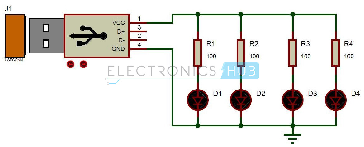
USB LED Lights Circuit Diagram
Circuit Components:
- USB
- Light Emitting Diodes – D1, D2, D3, D4.
- Resistors – R1, R2, R3, R4.
USB LED Lamp Circuit Design:
The circuit mainly consists of USB. USBs can be divided into mainly of two standard types – USB of ‘A’ type and USB of ‘B’ type. These different types of USBs connectors differ in their shapes .Type ‘A’ USB can be used with the upstream devices such as USB hub or host .Type ‘B’ USB can be used with downstream devices such as printers .These cables will have same number of pins but they differ mechanically. Many versions in USB were released. The first version USB 1.0 and 1.1 had the data rate of 12 Mbps.USB 2.0 has data rate of 480 Mbps.USB 3.0 is expected to have data rate of 4.8 Gbps.
Do you have any idea about the circuit – 3X3X3 LED Cube Circuit
USB used here is of type ‘A’. It has 4 pins. These pins are VCC, GND, D+, D- pins are the data pins. VCC pin outputs the voltage of 5V. The USB used here is of type ‘A’. This can be simply connected to the USB port of the computer.
LED is a semiconductor device with two leads. Generally LEDs are used for indicating. It is similar to a normal P-N junction diode. The energy emitted is in the form of light when applied with the required voltage, while normal P-N junction diode emits energy in the form of heat. The color of light emitted depends on the band gap of the semiconductor. The LEDs used here are normal LEDs. They have voltage drop of 3.6V. The current required by the LEDs is 40mA. Initially these LEDs are limited to the red color, later high power LEDs such as blue LEDs, white LEDs were developed.
A resistor of 100kohms is connected between the Light Emitting Diode and the USB. This acts as a current limiting resistor. As the LEDs require maximum current of 40mA to glow with full brightness, they are required to protect from current more than this. So for that a resistor is to be placed before the led to oppose the amount of current. The supply voltage coming from the USB is 5V and the current drop at the Light Emitting Diode is 40 milli amperes. The following formula can be used to calculate the resistor value.
R=V/I
where, the value of V is 5 volts and the value of I is 40 mA.
So, R= 5V/0.04A =125 ohms
But generally, 125 ohm resistor does not exist in real time. Therefore a resistor of 100 ohms is used instead of 125 ohms. Though it gives an output current of 50 mA, this can be tolerated by the LED.
How to Operate USB LED Lamp Circuit?
- Initially connect the circuit as shown in the circuit diagram.
- Now insert the USB to the port of the computer.
- You can observe the lamp glowing
- Now remove the USB from port.
- Now lamp is switched off.
USB LED Lights Circuit Advantages:
- This is simple and inexpensive.
- This is a portable lamp.
- No extra source is required.
Applications of USB LED Lamp Circuit:
- This can be used as an emergency light. Get an idea about Working of Automatic LED Emergency Lights Circuit.
- This can be used to work with laptop or computer without disturbing the others sleep.
- This can be used as a reading lamp.
Limitations of the Circuit:
- This gives low intensity of light as it has only four LEDs.
very nice
ReplyDelete