A stepper motor is a brushless and synchronous motor which divides the complete rotation into number of steps. Each stepper motor will have some fixed step angle and motor rotates at this angle. Here in this article, interfacing of stepper to 8051 and ULN 2003 is explained.
Stepper Motor Control using Microcontroller Circuit Principle:
The main principle of this circuit is to rotate the stepper motor step wise at a particular step angle. The ULN2003 IC is used to drive the stepper motor as the controller cannot provide current required by the motor.
Also Read the Related Post – PWM Based DC Motor Speed Control using Microcontroller
Stepper Motor Control using 8051 Microcontroller Circuit Diagram:
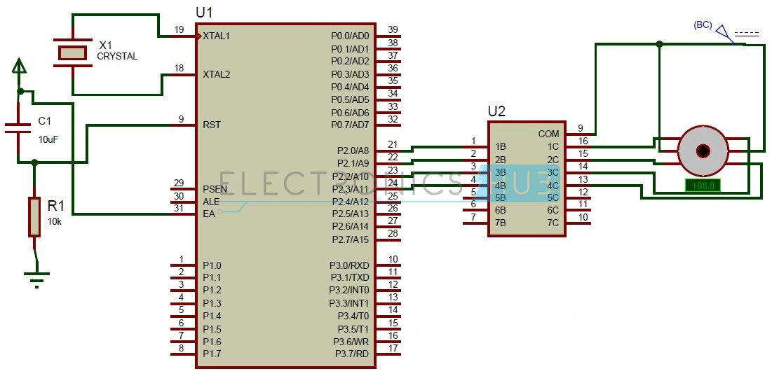
Circuit Diagram of Stepper Motor Control using AT89C51 Microcontroller
Circuit Components:
- AT89C51 micro controller
- ULN2003A
- Stepper Motor
- Crystal
- Resistor
- Capacitor
Stepper Motor Control using 8051 Microcontroller Circuit Design:
The circuit consists of AT89C51 microcontroller, ULN2003A, Motor. AT89c51 is low power, high-performance, CMOS 8bit, 8051 family microcontroller. It has 32 programmable I/O lines. It has 4K bytes of Flash programmable and erasable memory. An external crystal oscillator is connected at the 18 and 19 pins of the microcontroller. Motor is connected to the port2 of the microcontroller through a driver IC.
The ULN2003A is a current driver IC. It is used to drive the current of the stepper motor as it requires more than 60mA of current. It is an array of Darlington pairs. It consists of seven pairs of Darlington arrays with common emitter. The IC consists of 16 pins in which 7 are input pins, 7 are output pins and remaining are VCC and Ground. The first four input pins are connected to the microcontroller. In the same way, four output pins are connected to the stepper motor.
Stepper motor has 6 pins. In these six pins, 2 pins are connected to the supply of 12V and the remaining are connected to the output of the stepper motor. Stepper rotates at a given step angle. Each step in rotation is a fraction of full cycle. This depends on the mechanical parts and the driving method.
Similar to all the motors, stepper motors will have stator and rotor. Rotor has permanent magnet and stator has coil. The basic stepper motor has 4 coils with 90 degrees rotation step. These four coils are activated in the cyclic order. The below figure shows you the direction of rotation of the shaft. There are different methods to drive a stepper motor. Some of these are explained below.
Full Step Drive: In this method two coils are energized at a time. Thus, here two opposite coils are excited at a time.
Half Step Drive: In this method coils are energized alternatively. Thus it rotates with half step angle. In this method, two coils can be energized at a time or single coil can be energized. Thus it increases the number of rotations per cycle. It is shown in the below figure.
How to Operate this Stepper Motor Driver Circuit?
- Initially , switch on the circuit.
- Microcontroller starts driving the stepper motor.
- One can observe the rotation of the stepper motor
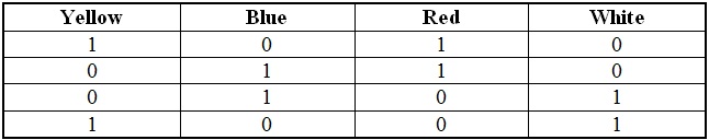
- The stepper motor has four wires. They are yellow, blue, red and white. These are energized alternatively as given below.
- In full step driving, use the following sequence
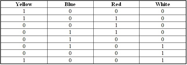
- To drive the motor in half step angle, use the following sequence
Stepper Motor Controller Circuit Advantages:
- It consumes less power.
- It requires low operating voltage
Stepper Motor Control Applications:
- This circuit can be used in the robotic applications.
- This can also be used in mechantronics applications.
- The stepper motors can be used in disk drives, matrix printers, etc.
No comments:
Post a Comment
some simple projects for Electrical&Electronics students