An LED is a special type of diode used as
an Optoelectronic device. Like a PN junction diode, it conducts when
forward biased. However a special feature of this device is its ability
to emit signal in the visible band of the electromagnetic spectrum. A
major concern to drive an LED is to provide an almost constant current
input. Often LED is driven using batteries or control devices like
microcontrollers. However these have their own disadvantages, for
example-low battery life etc. A feasible approach would be driving the
LED using AC to DC power supply. Though AC to DC power supply using
transformer is quite popular and widely used, for applications like
driving loads like LED, it proves to be quite costly and moreover it is
not possible to produce a low current signal using transformer.

Keeping in
mind all the factors, here we design a simple circuit driving a series
of LED from 230V AC. This is accomplished using a capacitor based power
supply. This is a low cost and efficient circuit and can be used at
homes.
30v LED Driver Circuit Principle:
The basic
principle behind this circuit is transformer less power supply. The main
component is the X-rated AC capacitor which can reduce the AC voltage
to a suitable amount. These capacitors are connected line to line and
are designed for high voltage AC circuits. This reduced AC voltage is
then rectified, filtered and regulated to produce a low voltage signal
to drive two LEDs in series.
230v LED Driver Circuit Diagram:
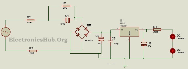
230 v LED Driver Circuit Diagram – Electronics Hub
230V LED Circuit Design:
Here the
main intention is to drive a series combination of LEDs by passing a
current of about 20mA through them. The first component to design the
circuit is a voltage regulator. This can be provided using a Zener
diode, but since Zener diode can get heated up easily, we prefer using a
voltage regulator IC which could provide accurate results. Here we use
LM78L12 voltage regulator IC delivering output voltage of about 12V at
maximum 100mA current.
The
minimum input voltage for the IC to maintain line regulation is around
18V. Keeping this in mind and the DC rectified voltage of around 20V, we
get the minimum negative peak of ripple voltage to be around 2V. The
ripple voltage is double the minimum peak and is around 4V. The value of
filter capacitor can be calculated keeping in mind the ripple voltage,
ripple frequency, quiescent current drawn by the regulator and the
maximum load current. This can be established mathematically as:
C = (Iq+Io)/(F * Vr)
For
Lm78L12, Iq is around 6mA, the required output current, Io is around
20mA, ripple frequency is double the line frequency of 50Hz and Vr is
around 4V. Substituting the values, we get capacitor to be around 65uF.
However keeping in account the facts of practical aspects, we chose a
47uF, 25V capacitor.
Since a
bridge rectifier is better in full wave rectification with more
efficiency, here we use a bridge rectifier with four diodes. The diodes
are selected keeping in mind the PIV rating of 100V. Here we use 1N4007.
For a
voltage of 230V and output current of 20mA, the required impedance is
about 11.5k ohms. For a frequency of 50 Hz, the value of capacitance is
seen to be around 0.13uF. However such a value is quite low and we
instead chose a value of 0.47uF producing output current of about 33mA.
(Based on calculations, a 1uF capacitor can produce current of about 72
mA.
How to Operate LED Driver Circuit?
The
resistors R1 and R2 limit the inrush current from the AC mains supply.
This AC voltage is further reduced by the AC capacitor C1 which drops
the voltage by around 210V. This reduced AC voltage is then rectified by
the bridge rectifier to obtain a rectified DC voltage of about 20V.
This DC voltage is then filtered by the filter capacitor which allows
the AC ripple signals to pass through it and the DC signal is thus fed
to the regulator IC. This filtered and rectified DC signal is then
regulated by the IC voltage regulator. The voltage regulator used here
ensures a maximum output current of 100mA, which is further reduced to
20mA using the resistor. Thus a regulated output of about 12V, 20mA is
used to drive two red LEDs.
The
resistor R1 acts as a bleeder resistor allowing the capacitor C1 to
discharge once the power is switched off. This provides a great deal of
safety.
Applications of 230V LED Driver Circuit:
- This circuit can be used for home lightening systems.
- It can be used as an indicator circuit.
- One can fix this circuit with the door bell to give indication.
Limitations of LED Driver Circuit:
- Since 230V AC supply is being directly used here, this circuit can be dangerous.
- This circuit is best suited for domestic applications using single phase supply. This is because in case of three phase supply, if any of the phases accidently touches the input terminal, it can prove to be quite dangerous.
- The capacitor can produce spikes at mains fluctuations.
No comments:
Post a Comment
some simple projects for Electrical&Electronics students