VU Meters are used in many applications like in discotheques to measure the level of audio signals. This level or magnitude of sound signal is termed as loudness. They are basically used to measure the loudness of sound signals or measure the noise signal. There are two ways to measure sound level of a signal.One of the ways is the use of sound pressure level meters which calculates the change in pressure of the sound signal on the principle that, at different frequencies, sound signals have different pressure levels.

Another way is displayed the loudness or sound level of the signal using visualized display. This is usually done using consecutive LEDs to indicate the sound level.
Both the methods measure loudness in terms of decibels, wherein one decibel is equivalent to ten times the logarithm of power of sound signal.
This article is about VU meter using LM3915 which is used to drive 10 LEDs. It is a dot/bar display driver and requires a 3V-25V supply. The LEDs are driven in 3DB steps. It consists of a ten stage voltage divider such that when each stage is reached, the matching LED will be illuminated.
10 LED VU Meter Circuit Principle of Operation:
The principle of operation lies with the working of LM3915. It basically consists of a buffer amplifier which drives a series of ten comparators. The input to the amplifier is the input analog voltage. Each comparator receives a reference voltage signal through a 1:10 potential divider arrangement and compares the input voltage with the reference voltage. Accordingly the corresponding LED connected to each comparator is driven incase the input voltage is more than the reference voltage. LM3915 can be operated in dot or bar mode, wherein the former means a single LED glows at one time and the latter means LEDs glow in continuous fashion. In other words dot mode represents the instantaneous value of audio wave.
10 LED VU Meter Circuit Diagram using LM3915 and LM324:
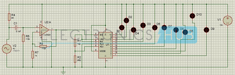
Circuit Diagram of LED VU Meter using LM3915 and LM324
10 LED VU Meter Project Circuit Design:
Designing the Circuit involves assigning proper connections to pins of LM3915. Pins 1, 10 to 18 are connected to cathodes of output LEDs whose anodes are connected to the power supply at pin 3. The pre-amplified audio signal from LM324 is given to pin 5 of LM3915. Pins 6 and 7 are shorted such that the current through pin 7 determines the current drawn by each LED. A resistor of 1.2K is connected between pins 7 and 8 such that a voltage of 1.25V appears between the pins. Pin 9 or the mode select pin is connected to pin 3 for bar mode operation.
Another important aspect of the design involves the audio preamplifier design. Here the audio preamplifier is designed around low power operational amplifier LM324. An advantage of this IC is that it can be used for wide range of bandwidth and hence can be used for audio applications. If one can recall audio frequencies are in the range of 20Hz to 20Kz. This implies the high filter section of the audio preamplifier must pass signals above 20Hz.
In other words, the cut off frequency is 20Hz. Selecting a value of 110K for the resistor; we calculate the value of capacitor to be 72nF. Here we use a 70nF capacitor.
Since this is a non inverting amplifier, gain of the amplifier would be Av = 1 + (R2/R1)
To achieve high gain, we select values of R2 around 110K and R1 around 1K.
10 LED VU Meter Project Circuit Operation:
Audio Signal from the microphone (seen here as an ac voltage source) is fed to the preamplifier section, where the high pass filter section allows the frequency above 20Hz to pass. This signal is amplified by the non inverting amplifier section where R8 is used for feedback. The amplified audio signal is then fed as input to the IC LM3915. Internal operation of LM3915 involves using comparing this signal with a reference voltage at each stage of a potential divider and accordingly driving the corresponding LED. The potential divider arrangement between pins 7 and 8 ensures a reference voltage of 1.2V which is fed to ten stage comparator circuit using 1:10 voltage divider. For each 3dB increase in the input signal, each comparator switches on the LED. Here we have connected mode pin to the V+ and voltage at this pin is at a level of V+ - 100mV and hence the bar mode operation takes place.
LED VU Meter Circuit Applications:
- It can be used in discotheques and other party places.
- This circuit can be modified to use high power lamps by adding opto-couplers in series with LEDs.
- The VU-meter can also be extended by cascading the IC with another IC LM3915
- These are used in audio applications, power meters, RF strength meters etc.
Limitations of the Circuit:
- In bar mode, large current drawn by LEDs cause voltage drops.
- Connection between common anodes of the LEDs and positive power supply should be at minimum distance because long wires can cause oscillations .
- Designing and assembling this circuit involves great deal of precaution as even a slightest deviation can result in enormous error.
No comments:
Post a Comment
some simple projects for Electrical&Electronics students