Electronic eye is also called magic eye. As the automation is emerging technology these days, just imagine a door bell that automatically rings when a person visit your home. This also provides security when any person is trying to enter into your home without your permission. Electronic eye is the electronic device that continuously watches if anyone is visiting your home. This article presents the circuit of electronic eye. Before going to know complete details about this circuit, get an idea about Light Activated Switch Circuit using LDR.

Electronic Eye Controlled Security System Circuit Principle:
The main principle of the circuit is to ring the door bell when there is any person at the entrance. Light on the LDR determines whether a person is present or not. When there is any object at the entrance, LDR is in dark and buzzer starts ringing and the LED starts glowing.
Circuit Diagram of Electronic Eye Controlled Security System:
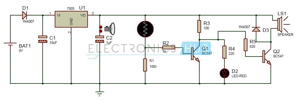
Electronic Eye Controlled Security System Circuit Diagram
Circuit Components:
- 7805 regulator U1
- Resistors R1
- 1N4007 diode D1
- Capacitors C1,C2
- BC 547 transistors Q1,Q2
- 7404 IC U2
- Light Dependent Resistor
- Buzzer BUZ1
- Light Emitting Diode D2.
- Bread board
- Connecting wires
- DC 9V battery.
Electronic Eye Controlled Security System Circuit Design:
This circuit can be divided into two parts. One is the power supply and the other is logic circuit. In the power supply 9v supply is converted to the 5v .The logic circuit operates the buzzer when any shadow falls on it.Power supply circuit consists of battery, diode, regulators and capacitors. Initially a 9v battery is connected to the diode. Diode used here is a P-N junction diode of 1N4007 series. In this circuit 1N4007 is connected in the forward bias condition .The main purpose of the diode in this circuit is to protect the circuit from negative voltages .There is a chance of connecting battery with reverse polarities which damages the circuit. So P-N junction diode connected in the forward bias allows the current to flow only in one direction and thus the circuit can be protected .There is some voltage drop across the diode. A voltage of 0.7V is dropped across the diode.A regulator is used for regulating the output voltage of the circuit .The regulator IC used here is 7805.78 represents the series and 05 represents the output voltage .Thus a voltage of 5v is produced at the output of the regulator .Two capacitors are used before and after the regulator .These two capacitors eliminate the ripples .Thus a constant voltage is produced at the output of the regulator, which is applied to the logic circuit.Also Read the Post: Automatic LED Emergency Light Circuit using LDRThe logic circuit mainly consists of Light Dependent Resistor, transistors,Op-amp IC and a buzzer. A 220KOhm resistor is connected in series to the LDR. Light dependent resistor will have resistance in mega ohms when it is placed in dark. This resistance value will decrease gradually when it is placed in the light. Thus there is a variation in the series resistances. When the LDR is in dark it has high resistance and produces the logic high value at the output .When the LDR is in light, the resistance value of the LDR decreases and at the not gate it gives logic low voltage.The op-amp IC used is LM 358.This IC compares the two inputs and produces an output which is applied to the transistor. Two transistor are connected to the buzzer from these resistances. The first transistor inverts the input from the op-amp. The second transistor drives the buzzer. The diode is placed for protection.Buzzer used here is a 5v magnetic buzzer. It has two pin at the output. One pin is connected to the not gate and the other pin is connected to the Light Emitting Diode.LED is used for indication only. When the output from logic gate is high buzzer starts ringing. Led also starts blinking.How to Operate this Electronic Eye Controlled Security System Circuit?
- Initially, connect the circuit as shown in the circuit diagram on the bread board.
- Now connect the supply voltage of 9v using battery.
- Place the Light Dependent Resistor in light .You can observe no sound is produced from the buzzer.
- Place the LDR in dark buzzer starts ringing. LED connected to the buzzer also starts blinking.
- As the intensity falling on the LDR increases sound produced by the buzzer increases.
Electronic Eye Controlled Security System Applications:
- This can be used in door bell circuits.
- This can be used in garage door opening circuits.
- Electronic eye can be used in security applications.
No comments:
Post a Comment
some simple projects for Electrical&Electronics students