Today fluorescent bulb and tube light are becoming outdated and they are replaced by LED lights as LED lights consume less power and have long life in comparison to fluorescent lamp and tube light. LED lights have many advantages over Fluorescent lamp and are mentioned at the end of this post.Here, we have described a simple circuit which you can easily made and install in your homes and will not only save resources but your energy and money will also be saved.


Mains Operated LED Light Circuit Diagram:
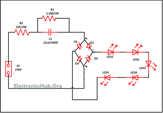
Mains Operated LED Circuit Diagram – ElectronicsHub.Org
Components used in this Circuit:
- Bridge rectifier – 1
- Resistor
- R1(2.M/1W) – 1
- R2(22E/1W) – 1
- C1(.22uF/400V) – 1
- LED – 5
Mains Operated LED Circuit Explanation:
This simple circuit is based on Bridge rectifier, resistor, LED and capacitor. All the components used in this circuit are easily and radially available in market. So make this circuit and install in your home and offices. Before understanding the working of circuit first have a look on the component description first.
1. A rectifier is an electronic circuit used for converting an alternating current (AC) to direct current(DC). And the process of converting alternating current to direct current by allowing one way electron flow is called as rectification. In full wave rectifier four diodes are connected in a circuit to form a bride. In this we are utilizing both positive and negative of AC.
A bridge rectifier contains four diodes D1, D2, D3, D4 connected to form a bridge as shown in figure. Hence this arrangement is known as a bridge rectifier.
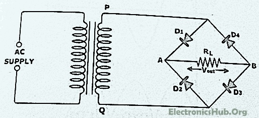
Bridge Connection of Diodes
Working of Bridge Rectifier:
The AC signal to be rectified is applied to the diagonally opposite ends of the bridge through the transformer. Between another two ends of the bridge, The load resistance RL is connected.
During positive half cycle of secondary voltage, The end P become positive and end Q negative. Thus Diode D1 and D3 will become forward bias and start conducting , while diode D2, D4 are reversed bias.
Diode D1 and D3 are in series with the load resistance RL hence current flows through RL as shown in figure.
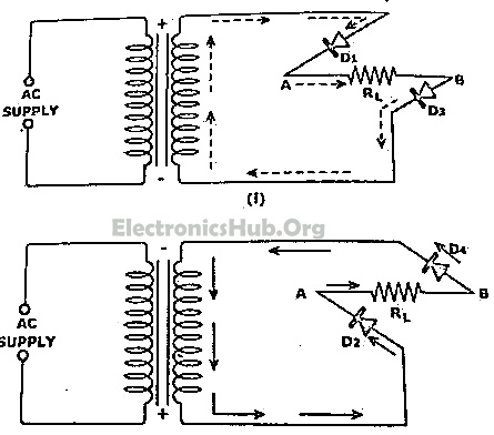
D1 and D3 Series Connection with Load Resistance RL
During negative half cycle of secondary voltage, the P end becomes negative and Q end become positive. Diode D2 and D4 are forward biased hence they start conducting . Whereas diode D1 and D3 are reversed biased.
Diode D2 and D4 are in series with the load resistor RL hence current flows through RL as shown in figure. It may be seen that again current flows from A to B through the load i.e. in the same direction as for the positive half cycle. Thus DC voltage is obtained across load RL . Output waveform of a bridge rectifier is shown in figure below. The advantage of Bridge rectifier is that its output is higher than of full wave and half wave rectifier.
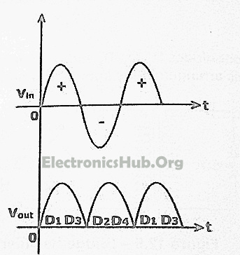
Output waveform of a bridge rectifier
2. Light emitting diode are different from other diodes as they emit light and hence referred as light emitting diode. LED are available in RED, GREEN, BLUE color.
3. All material have some type of opposition to the current flow. This opposition is called resistance. The resistance of a material is determine by the number of free electrons in the material. There are various type of resistor available such as carbon film, carbon composition, filament resistor and many more which can be used in an electronics or electrical circuit to determine the resistance.
Resistance of circuit depends upon p, L and A with the following equation.
R = p*(L/A)
4. The capacitor is a device that store electrical energy and capacitance is the amount of electrical energy stored at a given voltage drop by capacitor. A device specially designated to have a certain value of capacitance is called a capacitor. The capacitor has the ability to store electrons and release them at later stage. The capacitor is generally consist of two metal plate which are separated by a non conducting material called as dielectric.
5. Diode is an electronic device which allows current to flow only in one direction. Diodes are forward by joining N type and P type semiconductors. The N type semiconductor contains free electrons that move through the material. Similarly P type semiconductor contains holes. Electrons from the N type which are near the junction cross the junction and fill in the holes in P type material. Similarly holes near the junction of P type material, crosses the junction and occupy the place of electrons. A depletion layer is formed at the junction of the PN semiconductor.
6. Light emitting diode are different from other diodes as they emit light and hence referred as light emitting diode. LED are available in RED, GREEN, BLUE color.
Working of circuit is very simple. Assemble the circuit properly as shown in circuit diagram. Now apply AC mains. Resistor R2 is used as current limiting components. And resistor R1 is used with capacitor C1 so that it will discharge the capacitor which prevent lethal shock. Now this power supply is provides to bridge rectifier circuit which will convert the AC to DC and also reduces the voltage with the help of current limiting components. Now this power supply is passed to LED’s and LED connected at the output start glowing. You can use bridge rectifier available in market or you can make your own with the help of four diodes. Maximum you can use 20 LED’s.
Advantages of LED Bulbs:
- LED bulbs have 10 times longer life in comparison to fluorescent and incandescent lights.
- LED bulbs does not contain filament so there is less chances of damage.
- Common incandescent bulb become hot and generate lot of heat in the room while LED bulb prevents the heat build up and helps in reducing the air conditioning cost in room.
- Power consumption of LED lamp is approx. 2-17 watt 1/3 in comparison to fluorescent lamp. So if you LED bulb you can save much on your electricity bill.
- As power consumption of LED lamp is very less, use in solar panels is increasing.
- Many people are using inverters in their home and now they are using LED lights with inverters because this will also increase the time period for which inverters can support LED light.
- Initial cost of LED bulb is more in comparison to fluorescent bulb with they have long life and they can be easily move from one place to another without breakage and save electricity also. Therefore LED bulb is more efficient than fluorescent bulb.
- LED bulbs are not sensitive to temperature or humidity.
- LED bulb does not contain mercury also hence do not provide harm to environment also.
- LED lights will turn on instantly.
No comments:
Post a Comment
some simple projects for Electrical&Electronics students